
Holly and I have a lot invested in Sabado's electrical system. The 1,035Ah 24V LiFePO4 bank, the AC charging components, the DC/DC chargers, and the inverter all live in one compartment that we built under the owners bed. Heat is the enemy of every one of them.
We needed active ventilation in that space, not just passive airflow. What started as a simple two-fan setup grew into something more capable, and the control logic turned out to be more interesting than I expected. This post covers what we built and how it works.
The Problem
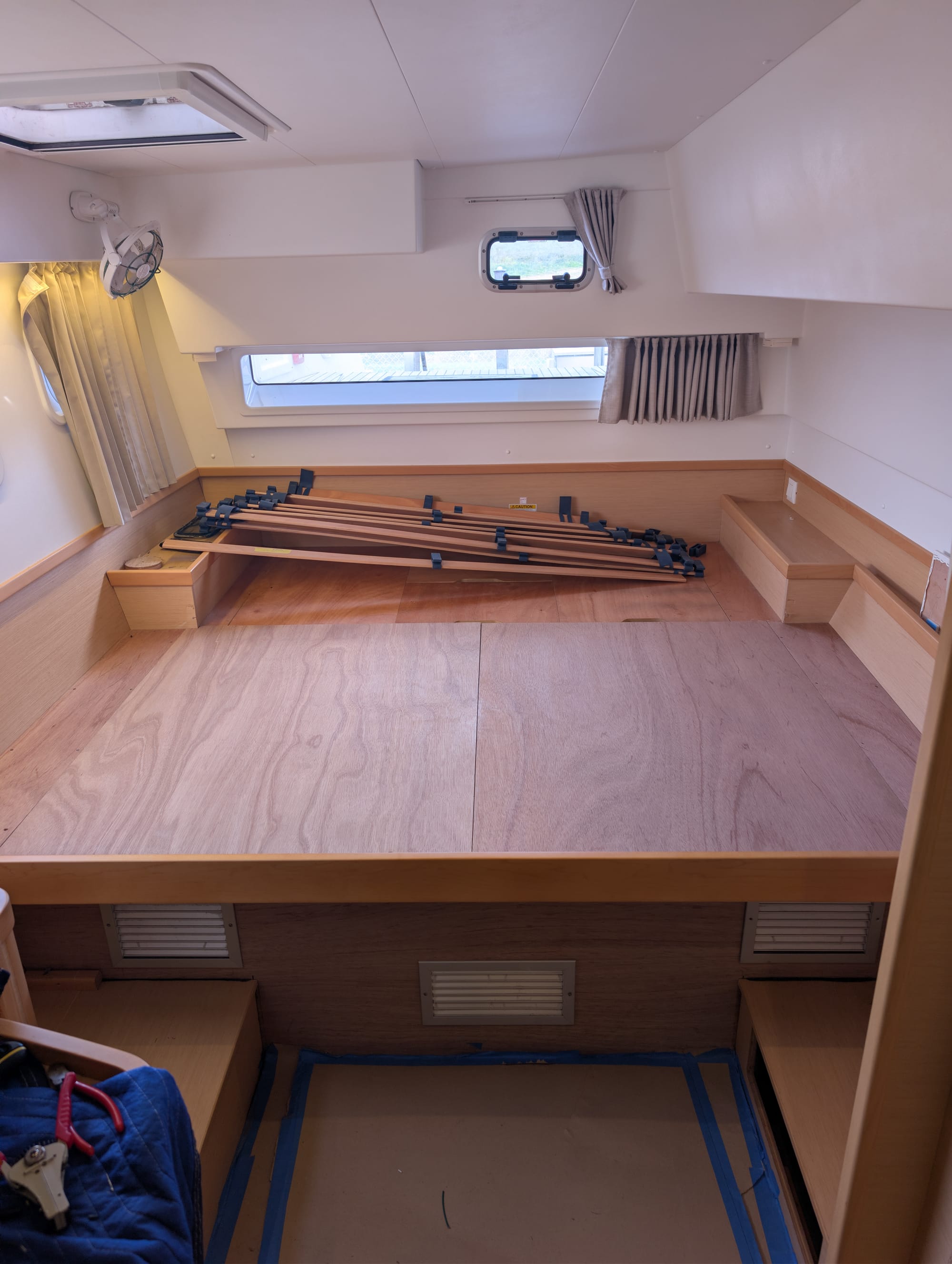
The electrical compartment on a Lagoon 42 isn't large so we decided to remove the bed on our side of the boat and build a new space.
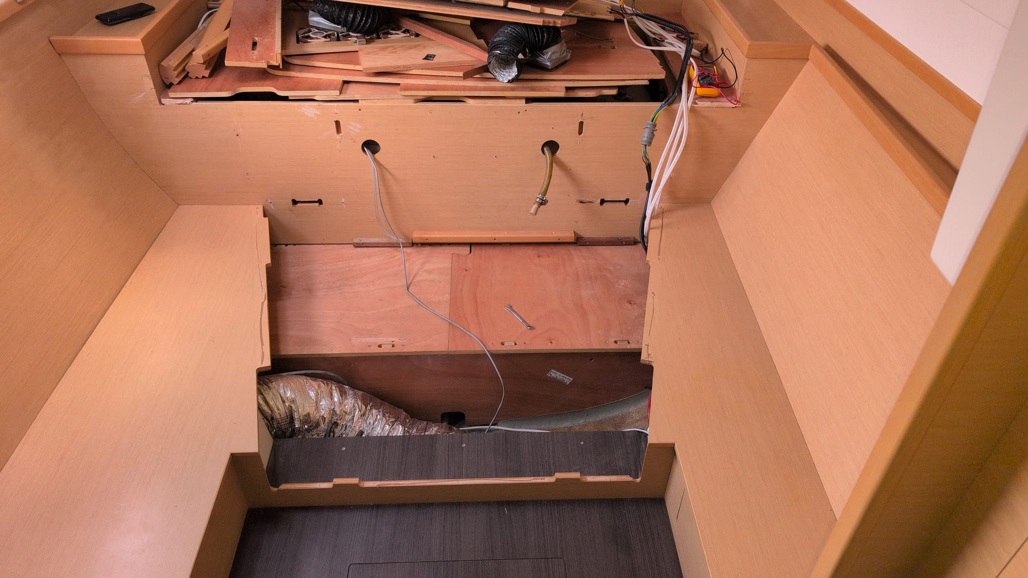
On a warm day at anchor with solar charging hard and the inverter under load, temperatures climb. We wanted ambient air moving through the space, cool in and warm out, without fans running flat out all the time and without managing it by hand. Also, it makes little sense running fans to cool the space with ambient air when the ambient air temperature is about equal to the temperature in the compartment.
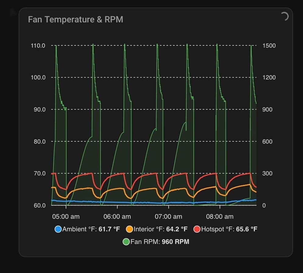
In New Zealand in late autumn, outside air is often 58 to 62°F. That's great for cooling, but it creates an awkward control problem. The delta between inside and outside can be large even when the interior isn't dangerously hot, and a naive controller will spin the fans up hard, pull cold air in, cool everything fast, then shut off. Ten minutes later it repeats. We watched exactly that oscillation play out in our first few iterations.
We also run a condensate pump for the AC units, so it made sense to manage that on the same controller but we’ll discuss that in a later post.
The Hardware
Five Noctua PWM fans, four blowing ambient air in and one extracting warm air out. PWM gives us speed control from roughly 20% to 100% instead of just on/off, which matters when you're living with the noise.
- Fans: Noctua NF-F12 iPPC, spec'd at 3000 RPM
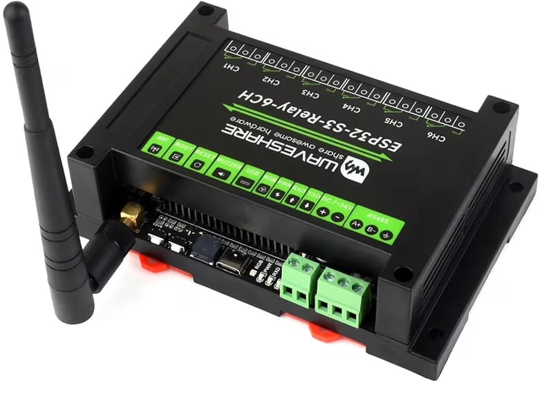
- Controller: ESP32-S3 on a Waveshare 6-channel board with relay outputs, which also drives the condensate pump relay
- Temperature sensors: Three one-wire sensors on a single bus:
- Ambient, outside the compartment, measuring incoming air
- Interior, general compartment air temperature
- Hotspot, positioned at the highest heat-generating component
- Fan RPM: Pulse counter on the tach wire, so we're reading actual fan speed rather than trusting the PWM command
The Software: ESPHome
The controller was flashed to runs ESPHome, which integrates natively with Home Assistant over the local network. Firmware is YAML with embedded C++ lambdas for the logic, which is enough for real embedded control without dropping to full ESP-IDF.
Temperature-Based Control
The control function runs every 10 seconds. It takes the higher of hotspot and interior, computes the delta above ambient, and maps that to a PWM level with an exponential curve:
float excess = delta - HYSTERESIS_ON_DELTA_C;
float max_excess = 13.5f;
float k = 0.050f;  // curve shape, lower = gentler ramp
float raw_f = 1.0f - std::exp(-k * excess);
float max_f = 1.0f - std::exp(-k * max_excess);
level = 0.2f + (0.8f * (raw_f / max_f));
The exponential response is gentle at small deltas and steepens as the delta grows, which is a much better fit than a linear ramp. k sets the steepness. We started at 0.087 and pulled it down to 0.050 after watching the fans overshoot in cool ambient conditions.
Hysteresis
Turning the fan on at 70°F and off at 70°F gives you chatter. We use hysteresis at two levels:
- Temperature threshold: won't start until interior reaches 70°F, stays on until it drops to 65°F
- Delta threshold: won't start until delta above ambient is at least 2.7°F, stays on until delta drops below 0.5°F
const float MIN_EFFECTIVE_ON_C  = 21.1f;   // 70°F, start threshold
const float MIN_EFFECTIVE_OFF_C = 18.33f;  // 65°F, stop threshold
const float HYSTERESIS_ON_DELTA_C  = 1.5f; // 2.7°F to start
const float HYSTERESIS_OFF_DELTA_C = 0.3f; // 0.5°F to stop
The Oscillation Problem
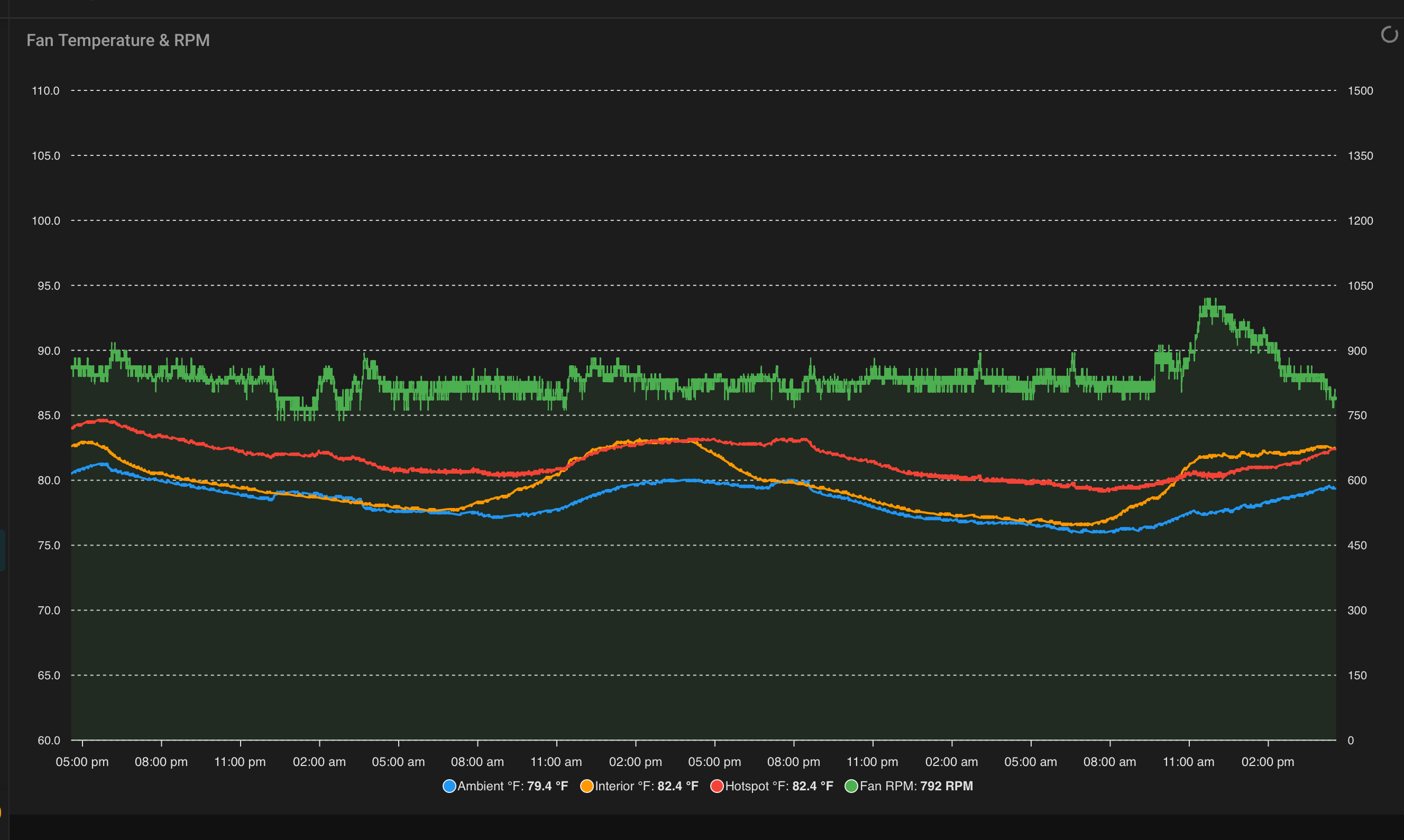
Hysteresis alone wasn't enough. With ambient at 59°F and interior at 70°F, the delta is nearly 11°F, which was enough to drive the fans hard. They'd cool the compartment fast, the delta would collapse, the fans would stop, temperatures would climb, and the whole thing would repeat. The RPM trace on the chart was a clean sawtooth.
Three changes fixed it:
PWM cap below 72°F interior. If the interior hasn't reached 72°F there's no reason to push. Cap at 25%, which on 3,000 RPM fans is about 750 RPM. Enough to move air steadily without overcooling.
const float LOW_TEMP_PWM_CAP_C = 22.22f;  // 72°F
const float LOW_TEMP_PWM_CAP   = 0.25f;   // 25% max
if (level > LOW_TEMP_PWM_CAP && std::max(interior, hotspot) < LOW_TEMP_PWM_CAP_C) {
  level = LOW_TEMP_PWM_CAP;
}
Asymmetric slew rate limiting. PWM can rise 5% per 10-second cycle but fall 20% per cycle. Conservative about adding power, responsive about shedding it. This keeps a transient delta reading from kicking the fans to high speed.
Minimum run time. Once the fans start they run at least 10 minutes before they're allowed to stop. Kills the rapid cycling and gives the compartment time to settle before the next on/off decision.
Failsafe
If the interior and hotspot sensors both return NaN for more than 90 seconds, the system drives the fans to 100% immediately and bypasses all the ramp logic. A Home Assistant persistent notification fires at the same time. Running the fans flat out on a sensor fault is the right failure mode. Leaving the compartment unventilated is not. It might sound like a jet engine but it’s better to be safe.
Ambient going NaN is handled differently. The controller falls back to the last known ambient reading and posts a warning, but doesn't trigger failsafe, since a stale ambient value is still usable for a delta calculation.
The Home Assistant Dashboard
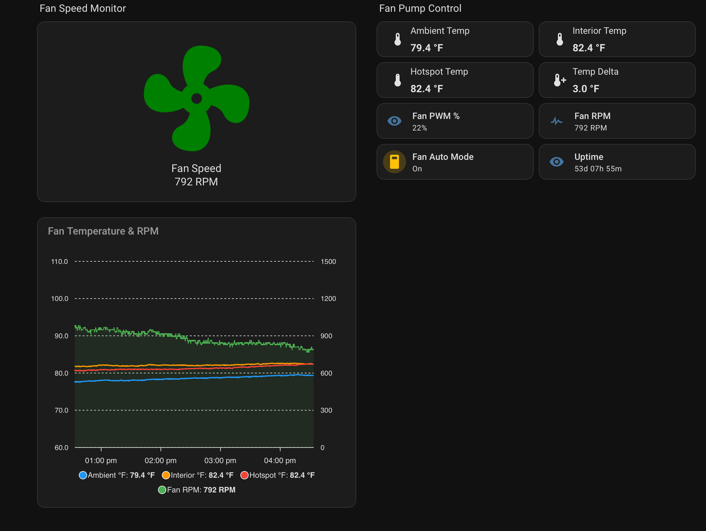
This is where it comes together. We built a dedicated Temps dashboard that gives us the whole picture at a glance.
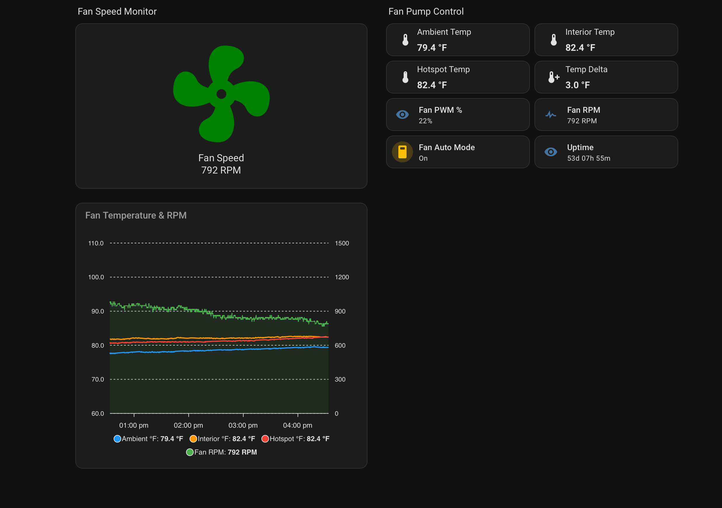
The fan speed monitor drives an animated fan graphic that spins proportionally to actual RPM. Small touch, but it makes the state of the system obvious from across the salon.
Below it, an ApexCharts card plots all three temperatures against fan RPM on a shared four-hour timeline. This chart is what drove nearly every tuning decision we made. Seeing the RPM trace alongside the temperature lines makes overcorrection immediately obvious. You can watch interior and hotspot dip as RPM spikes, then watch the cycle restart.
What We Learned
Tune for your worst-case ambient, not your typical one. The oscillation only appeared in cool ambient conditions. In warm weather the system behaved fine and we would never have caught it. Stress the control logic across the full ambient range you expect to see.
Exponential beats linear. A linear PWM ramp gives you too much fan at low deltas and not enough at high ones.
Asymmetric slew rates are the correct behavior for a cooling system. Slow to add power, quick to shed it.
Instrument before you tune. The RPM-against-temperature chart made the failure mode legible in about thirty seconds. Without it we'd have been guessing.
Is It Working?
So far, yes. The compartment is holding well within limits, the fans aren't cycling, and we have full visibility from anywhere on the boat. The real test comes as we move into warmer conditions in Fiji, where the ambient delta problem inverts and the fans will actually need to work.
Still tuning. But having real data, automated control, and proper alarming on a critical system is the right posture for bluewater cruising, where there's nobody to call.
If you would like to give this a try, we’ve posted the code for our crew in the documents section. Have a go at it and let us know how you implement it.